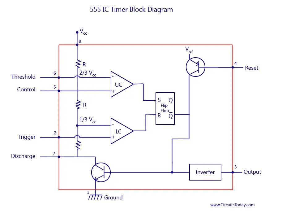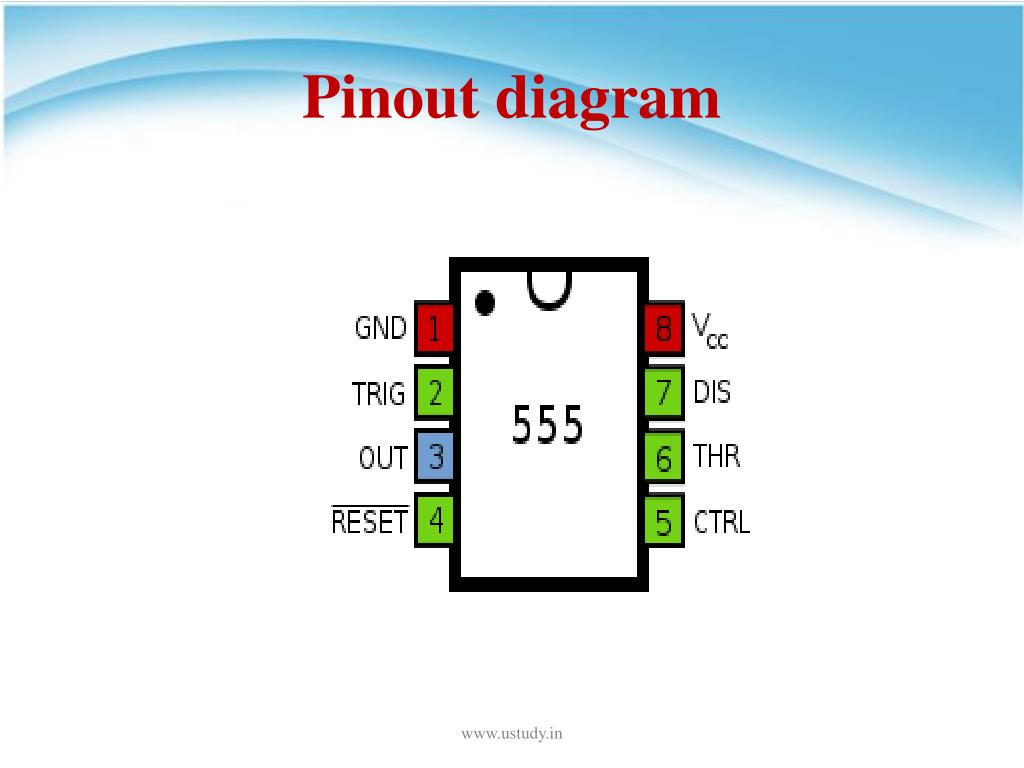

If pin 2 is “HIGH”, pin 6 can be HIGH or LOW. It will go LOW when pin 6 detects 2/3 the supply voltage. This pin has a very high impedance (about 10M) and will trigger about 1uA. It detects 2/3 of the supply voltage to turn IC off, make output LOW only if pin 2 is HIGH. We can adjust frequency via an external pot. The capacitor to this pin removes external noise.Īlso, the voltage applied to this pin will vary the timing of the RC network (quite considerably). Normally we often see this pin connect to the ground via 0.01uF to 0.1uF capacitor.

It must be taken below 0.8v to reset the chip. Maybe internally connected HIGH via 100K Resistor. If it is HIGH (about the supply voltage) and deliver up to 200mA. While the pin 2 LOW, this pin has a very high impedance (about 10M) and will trigger about 1uA. It will detect the 1/3 of the supply voltage. Then, drive the Output stage to pin 3 output. In this diagram, you can see a free-running Flip-Flop which is triggered via pin 2(Trigger) to the comparator and pin 6 to the comparator.

The schematic is somewhat simplified, block diagram making the operation of the circuit slightly easier to understand. Obviously, it would not be worthwhile to make this circuit from the normal components. This full schematic diagram is mainly to show its complexity. The 555 timers are contained in a tiny 8-pin Dual-In-Line package that looks like a 741 op-amp or LM386 audio amplifier.Īlso: 555 Siren sound Generator Full 555 schematic Read related: AC dimmer for LED Bulbs using IC-555 555 pinout Temperature stability is better than 0.005% per ˚C.TA-Operating free-air temperature: 0 – 70C.Such as, with a 5V supply, the output is compatible with TTL inputs. The oscillator does not change frequency even VCC changes.Can output up to 200 mA of current (I O).Operates in both astable and monostable modes.Can accurate time delays or oscillation.When the price falls it will be a very good choice as it consumes only 120uA. When operating as an oscillator, we can consider the power consumed to be equal to that of an LED.Ī CMOS version has been introduced with part number LM7555. The NE555 takes 10mA from the supply when the output is “high”, and 1mA when the output is “low”.

Therefore, we must especially attend to this point, when designing for battery operation. But its power consumption is more than a CMOS chip. Thus, it is not sensitive to static electricity. They can give off time from microseconds to several hours. The NE555 is one of the handiest chips to be invented and specially designed to operate as a multivibrator. The 555 (read “triple five”) is a short way of saying LM555 or SE555 or NE555. GET UPDATE VIA EMAIL 555 timer datasheet Description


 0 kommentar(er)
